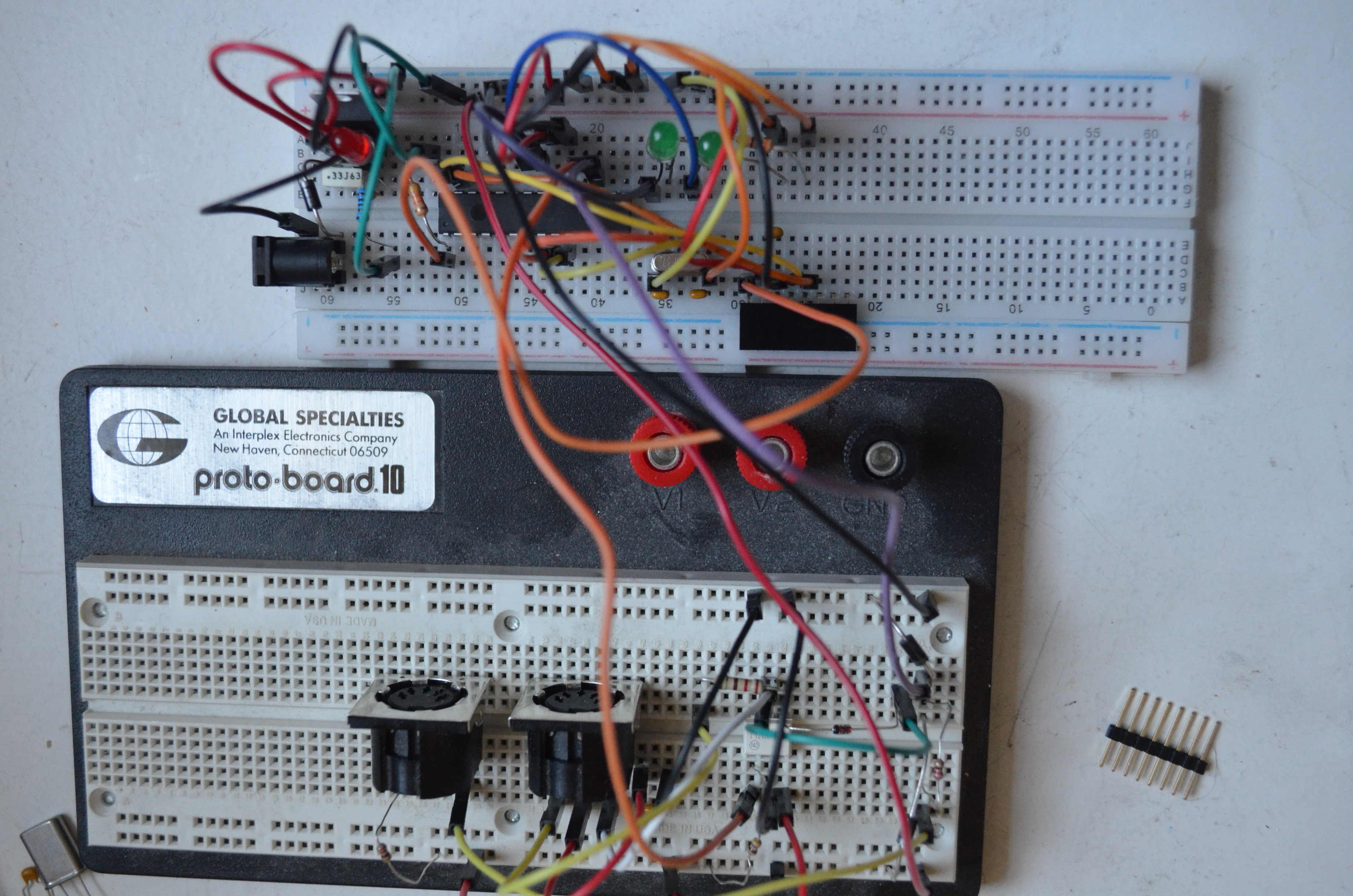
After a successful demonstration of viability of a PIC-based solution of my MIDI processor using a demonstration board (Phase 1), it is time to move on to Phase 2: a prototype of the actual ‘production circuit’. The prototype is still built on a breadboard, but consists of the actual circuit and firmware that I hope to eventually turn into a PCB. This production circuit has some considerations that are different from, or could even be completely ignored in, the demonstration board environment; which we'll discuss here.
Not having the support of the pre-programmed bootloader on the demonstration board means that we'll need a proper solution for programming the board. The obvious answer here is to use Microchip's own PICkit 5 programmer/debugger. Granted that at $95 it's a little bit of an investment for a hobby project, but seeing that it's stated to support Microchip's entire architectural range I may eventually be able to amortize my investment if I'm ever able to experiment with any of these. On the host side, the PICkit has a USB Type C connector but connects to the PC through a standard Type A plug. On the device side is a simple 8-pin Single In-Line (SIL) header that supports Microchip's proprietary In-Circuit Serial Programming (ICSP) directly, and other protocols (JTAG, SWD, AVR) through an adapter board. We'll just need ICSP for this project.
The PICkit User's Guide is very helpful here in designing the programmer/debugger interface. §3.3.1 and §3.3.6.2 show the five lines that need to be connected, and the pull-up resistor for VPP/MCLR that keeps it disabled when the programmer is not connected; and additionally a small decoupling capacitor between VDD and VSS. I used 43 instead of 47 kΩ because I had it available.
There is a choice to be made between standard (perhaps, ‘legacy’) programming that uses a programming voltage VPP higher than VDD, and a newer Single-Supply Programming (SSP) method that just uses VDD; these are also sometimes distinguished in the documentation as High- and Low-Voltage Programming (HVP/LVP). The PICkit seems to support both, so the supposed challenge of needing a second supply voltage isn't a problem in practice. The single-supply method has a technical disadvantage in having to dedicate a RB5/KBI1/PGM pin to the PGM signal, which also isn't really a problem in this application. Because it wasn't immediately clear to me how I should manage the PGM signal itself, I just opted for standard high-voltage programming, which has worked fine.
The 18F2450 doesn't have the same internal oscillator option that the 18F45K50 on the demonstration board had: notably, the '2450 will internally only generate 31.250 kHz. This means we have to use an external crystal oscillator or ceramic resonator. Note that for this application I don't need to abide by the various restrictions for supporting USB, so I could pretty much choose whatever frequency I wanted. Since a 4 MHz clock worked well on the demonstration board prototype, I decided to go up one step higher and use an 8 MHz crystal oscillator and create some headroom for future expansion.
The documentation warns to use a “parallel cut” crystal. I'd never heard of this term before, and indeed the first hit searching for it also was in relation to a Microchip 18F device. Answers found suggest that ‘parallel’ is in fact common, and that if a ‘load capacitance’ is given you can assume that it is. Finally, DigiKey's component selector has a filter for “Load Capacitance” that lists a bunch of numerical values and, at the end, “series”; so I think I know how to select the right crystal.
In the demonstration board implementation I used Idle as a power-saving mode: this shuts down the CPU but keeps the peripherals running. In that case I needed the peripherals for the Timer to blink LEDs, but since I don't actually need it in the application I could even use Sleep mode. The real point here is that since I'm not designing a battery-powered device, I really don't need any ‘power-saving’ mode at all. Also note that TCSD < 10 µs on top of the time it takes to service the interrupt, so the added latency is really negligible. I've kept the interrupt-driven design under Idle because it seems the cleanest solution.
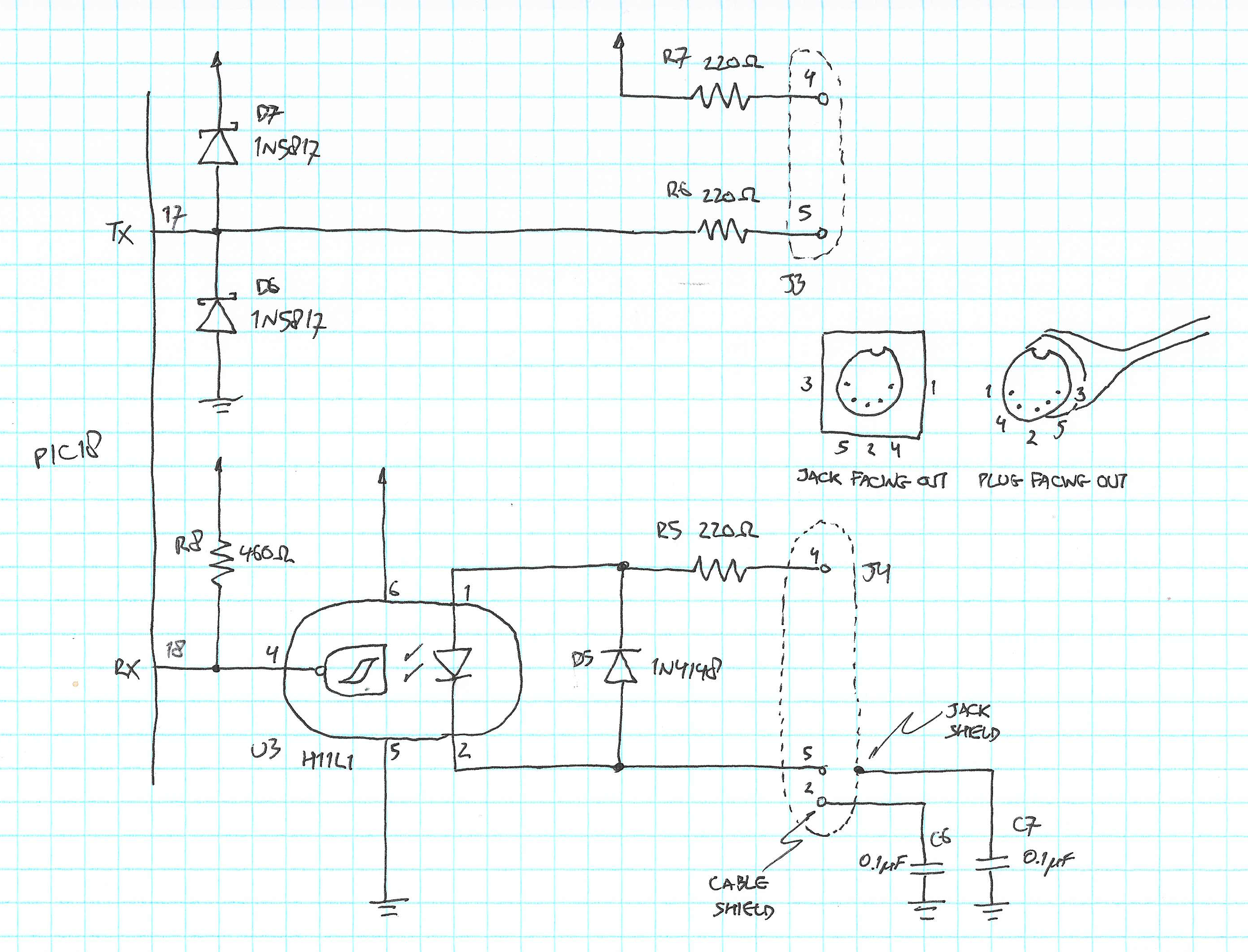
As mentioned before this will be powered from an AC adapter, so the usual 7805-based supply will work. A thought occurred to me here: I had put a Schottky diode on the PIC transmit pin with the idea that an inadvertant overvoltage applied externally to the line would flow onto the power supply line instead of the I/O pin, and thereby protect the microcontroller; but never really resolved the question of what would absorb that overvoltage. Why not connect the cathode to the input of the 7805 and have the regulator deal with it? This is a technique I would experiment with before using.
I want a red LED ‘power’ indicator and two green ‘function’ indicators; one to show play/stop mode and one for a transient ‘MIDI data received’. I had a bunch of LEDs lying around that I can't readily find data sheets for, so I randomly picked some and tried resistor values for reasonable current and visibility:
Will use the exact circuit from the demonstration board prototype.
We need a barrel-type power connector (I found a very nice reference here); but be careful to find one that fits a breadboard. Selecting the mounting type as “through hole, right angle” and ‘termination’ as “solder” leads for example to the PJ-102AH with leads that resembles DIP packaging. The thin ends of the leads are 1 mm/.04"; compare this with the DIN connectors I already use that have even fatter pins at 1.24 mm and .05".
We also need an 8-pin female SIL header for ICSD; technically only 5 pins are needed, but I'm getting all 8 to reduce opportunities for misaligned connections.
Finally, we need the two DIN jacks from the MIDI circuit.
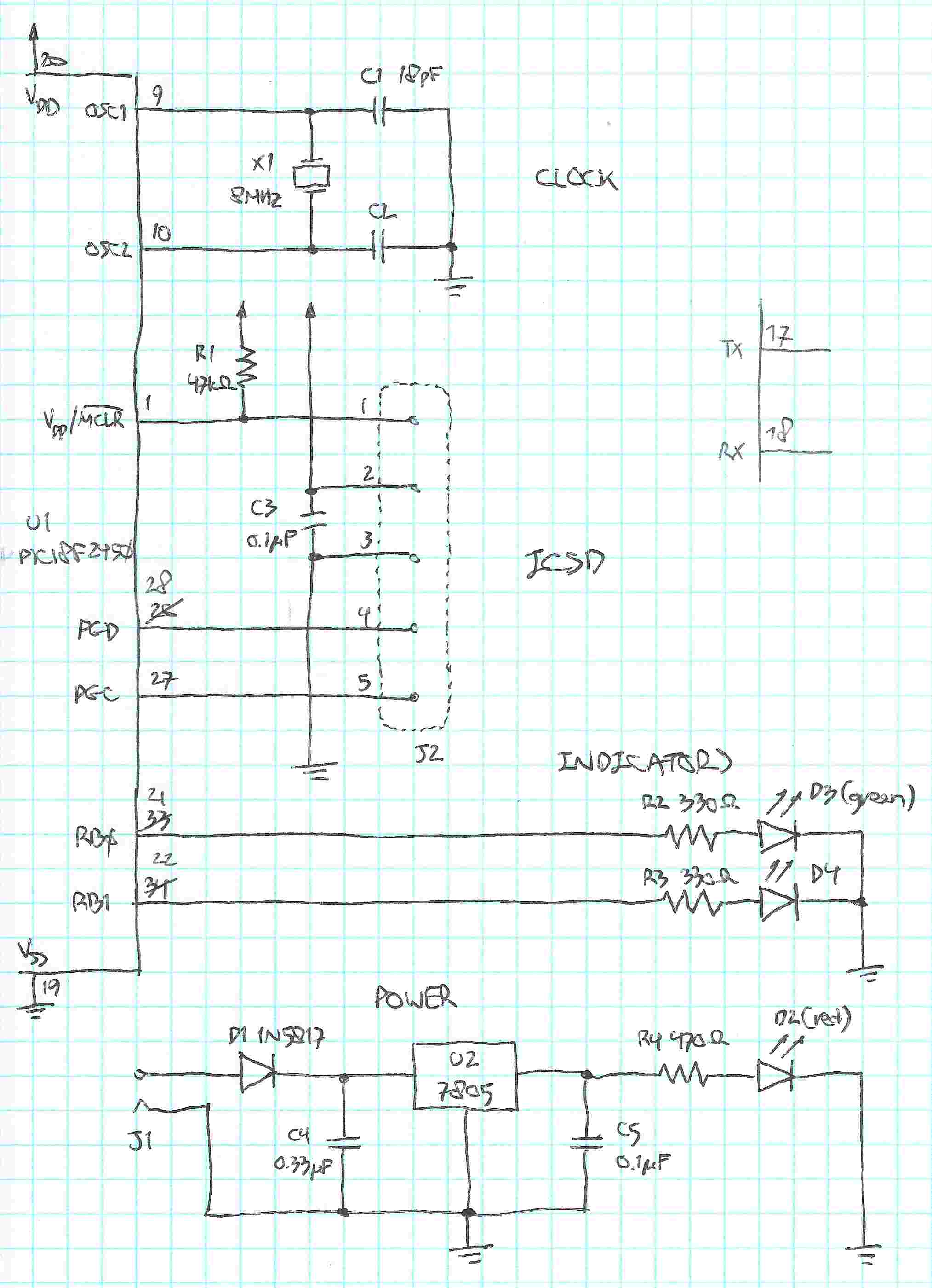 This is in addition to the schematic for the MIDI circuit we built in the demonstration board prototype,
which I've added here for completeness and with part designators:
This is in addition to the schematic for the MIDI circuit we built in the demonstration board prototype,
which I've added here for completeness and with part designators:
The firmware previously developed for the demonstration board needed only minor adjustments because of the different processor; and because of doubling the processor clock. See the PIC-MIDI-Processor project on GitHub.
Note that in the MPLAB X IDE you debug in ‘debug mode’ through the Program Device for Debugging Main Project menu item; but run in ‘production mode’ through Program Device for Production Main Project.
The prototype works as expected: pressing ‘play’ on the ADAT digital recorder triggers the Elektron drum machine, and lights the play/stop indicator LED D4 (RB1); pressing ‘stop’ also stops the drum machine and clears D4.
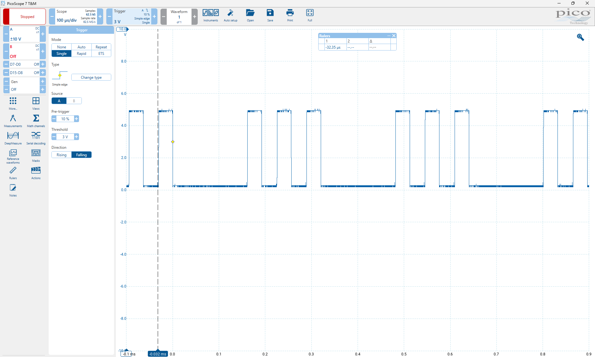
Through a loopback cable we can see how the output signal on the TX pin ends up being received on RX:
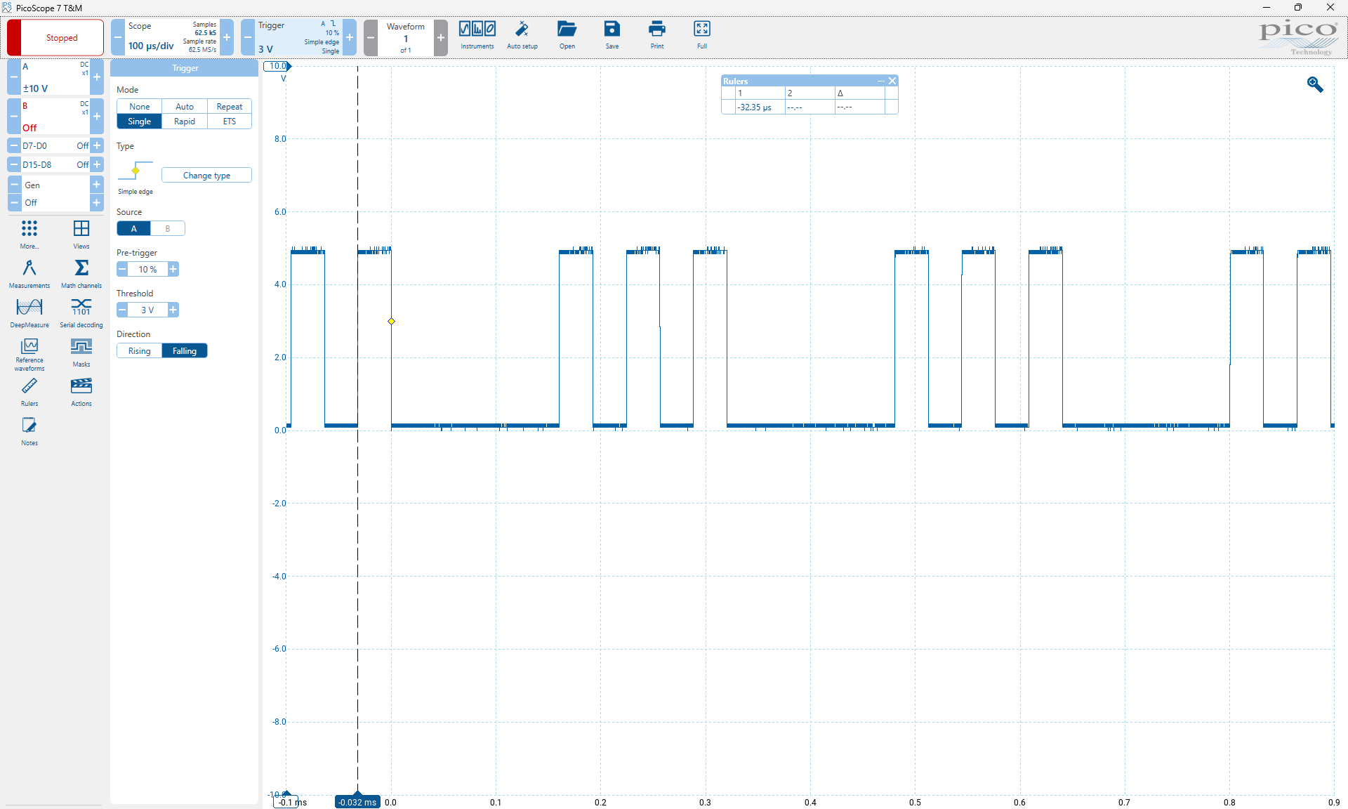
Zooming in we can visualize and measure the rise time:
.png) This measures as < 0.5 µs, well below the 2 µs requirement
(corresponding to one horizontal division of the scope trace) of the MIDI specification.
This measures as < 0.5 µs, well below the 2 µs requirement
(corresponding to one horizontal division of the scope trace) of the MIDI specification.
All pages under this domain © Copyright 1999-2024 by: Ben Hekster