A while back I jumped into the world of embedded systems, analyzing and eventually solving an actual problem I was having getting my MIDI equipment to interoperate. I used an evaluation board based on an ARM microcontroller from Nordic Semiconductor, with no particular reason for choosing that board other than easy availability, and adequate tutorials and documentation. Even though the board with its microcontroller makes up a complex piece of equipment that has a fairly steep learning curve for a newcomer, the documentation from ARM and Nordic in particular is so good, with such good tooling developed around it, that I don't regret taking that approach as a learning path.
It was always clear however that using a Bluetooth-enabled ARM controller was massive overkill for the MIDI processor I was building. On top of that the UART that I actually did need for MIDI was already used by the board to support USB, forcing me to use an auxiliary SPI/UART bridge and making the circuit even more complex than it needed to be. It was a fun project to learn from, but nowhere close to a proper ‘solution’. The final nail in the coffin was that ‘productionalizing’ this solution would have required me to start learning SMD soldering, which I'm desperately trying to avoid.
So I'd always planned to revisit the project. The requirement for a through-the-hole component eliminates ARM from consideration. I investigated a couple of alternative architectures, finally settling on PIC from Microchip; again, mostly because of product availability and documentation. (I really wanted to use Zilog for nostalgic reasons, but the Web site doesn't suggest it as a serious company anymore.) Microchip has a variety of microcontroller families available; an 8-bit system seemed adequate for a simple project like this. I picked the PIC18 family because of USB support which I'm hoping to add in the future, and settled on the PIC18F2450; partly because Microchip has a demonstration board based on the very similar PIC18F45K50.
I plan to get to the final product in three phases:
Some notes on the demonstration board.
The PICDEM FS USB has at least two versions: the original DM163025 and the revised DM163025-1. The documentation covers both but is fairly clear on distinguishing between the two; but it turns out a lot else changed since then, and the documentation hasn't kept up since it was last updated in 2013:
All of this this perhaps gives a hint that things will start going wrong.
While the product page cheerfully states that
The demo kit provides all of the hardware needed to demonstrate and develop a complete USB communication solution.
,
in 2024 that is really only technically true.
I point this out because the board that I received differs significantly in software and configuration,
to a point where it unnecessarily impedes getting to use it.
Summarizing my observations getting it all tow work: I tried locating a version of the legacy IDE that would work but was unsuccessful, so ended up using the latest version of the current MPLAB IDE X. There doesn't seem to be any option to download the legacy C18 compilers with MPLAB IDE X, so here as well I ended up just using the latest version of the current XC8 compiler. I downloaded a version of MLA (mla_v2018_11_26) to get access to the programmer that works with the USB-based bootloader it ships with. The programmer utility is in apps/usb/device/bootloader/utilities.
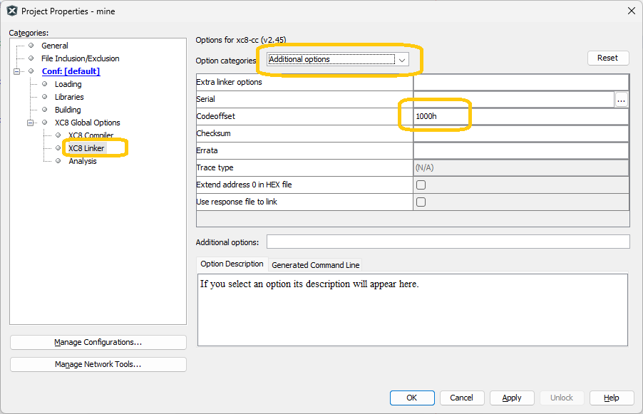
The board ships with a USB-accessible bootloader. Because of the presence of the bootloader, user code has to be mapped further down in the address space past where the bootloader is. The legacy C18 compiler (the one referred to in the documentation) used linker scripts to define the location of the reset and interrupt handlers; the XC8 compilers don't use linker scripts explicitly through some similar configuration can be found found in 'Packs', which are shipped with the IDE and don't appear to be intended to be editable. Instead, the project properties provide access to a ‘code offset’ setting:
The bootloader appears to write-protect itself, so forgetting to do this or getting the value wrong fortunately does not destroy it; but obviously your code needs to be exactly where the bootloader expects it to be for it to be reachable. The host bootloader tool however issues no diagnostic alerting you that part of your code is not being flashed: it will just fail in inexplicable ways. Fortunately, the documentation clearly states that the code offset value should be 0x0800.
Unfortunately, this value is also wrong. After a long process of investigation (including manual disassembly of some of the bootloader code itself) I found that, on my board at least, the actual location is 0x1000. This is a crucial bit of information, and without it nothing will work properly.
| Address | Register | Value (hexadecimal) | Value (binary) |
|---|---|---|---|
| 0x300000 | CONFIG1L | 0x21 | 00100001 |
| 0x300001 | CONFIG1H | 0x08 | 00001000 |
| 0x300002 | CONFIG2L | 0x1F | 00011111 |
| 0x300003 | CONFIG2H | 0x3E | 00111110 |
| 0x300005 | CONFIG3H | 0x91 | 10010001 |
| 0x300006 | CONFIG4L | 0x81 | 10000001 |
| 0x300008 | CONFIG5L | 0x00 | 00000000 |
| 0x300009 | CONFIG5H | 0xC0 | 11000000 |
| 0x30000A | CONFIG6L | 0x0F | 00001111 |
| 0x30000B | CONFIG6H | 0xE0 | 11100000 |
| 0x30000C | CONFIG7L | 0x0F | 00001111 |
| 0x30000D | CONFIG7H | 0x40 | 01000000 |
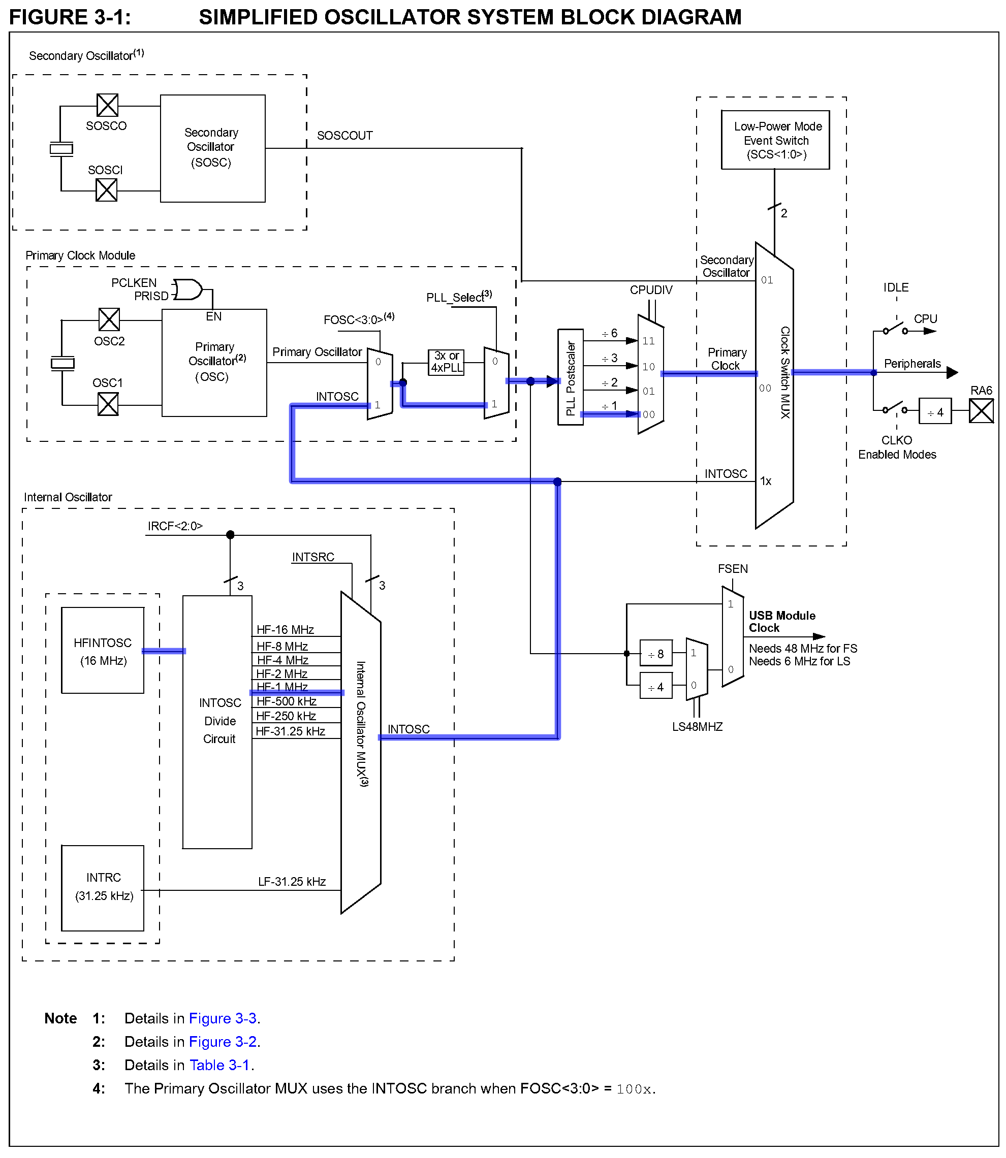
The configuration bytes show that the “clock setup” diagram for the DM163025-1 version of the board in Figure 1-3 is not correct. The following extracted from the data sheet shows the actual clock path, which leads to a system oscillator frequency of 1 MHz.
The MIDI circuit is pervasive by now and mostly boilerplate:
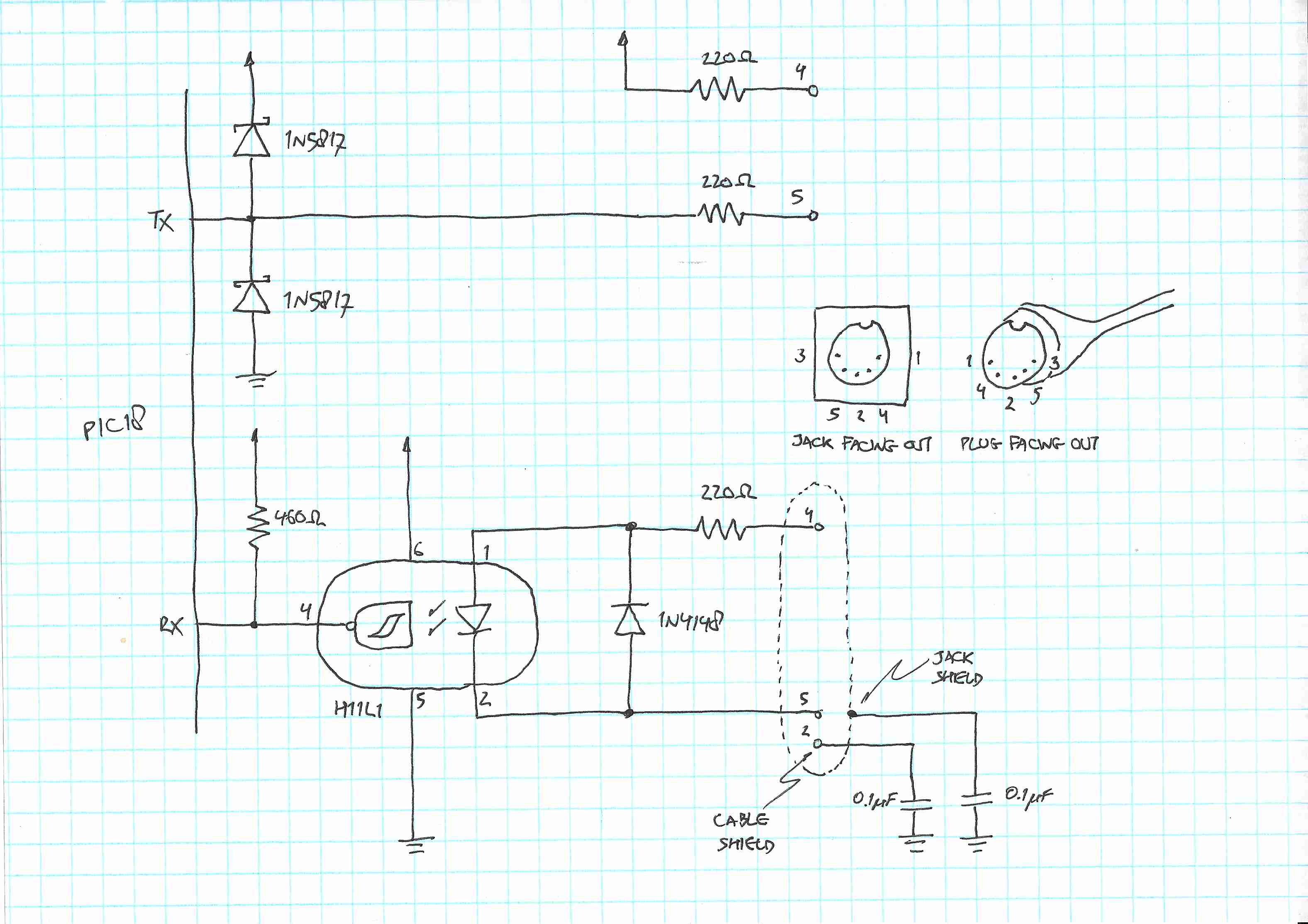 In practice I wasn't able to connect the jack shield capacitor due to physical space constraints.
In my original starter project I had an extra optocoupler that I repurposed to protect the microcontroller transmit GPIO; here I used Schottky diodes instead. I'll admit that I'm on the fence about all of this. My theoretical concern here is that an external pin in a ‘musical instrumentation environment’ could inadvertently get connected to out-of-range voltages. The Schottky diodes would then switch on before the absolute maximum ratings of the microcontroller pin are reached. The 220 Ω resistor here also serving as a current limiter.
This comes at the cost of up to 1 mA of leakage current and on the order of 100 pF capacitance; this is negligible as long as I'm not planning on driving this off battery power. The diodes just pass the overvoltage problem to the power rails, which I probably should deal with (but haven't) using a Zener diode. Of course, extreme out-of-range voltage may damage the diode, possibly rendering the board useless anyway. So the justification for this circuitry is predicated on the existence of a realistic risk that fits right in that window.
With the circuit as given, a logical ‘0’ should pull the requisite 5 mA:
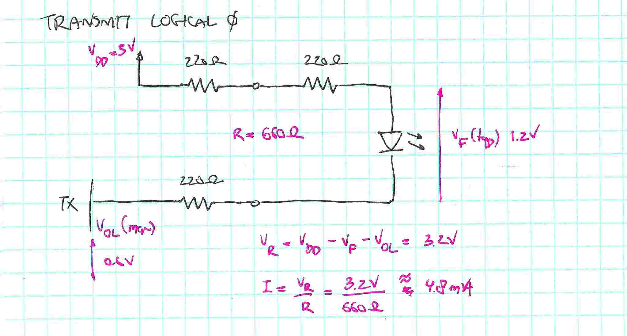 Also, the resistors sufficiently limit supply current in case of a short;
but barely limit current enough on the transmit pin: the absolute maximum sink/source current on an I/O pin is 25 mA.
Also, the resistors sufficiently limit supply current in case of a short;
but barely limit current enough on the transmit pin: the absolute maximum sink/source current on an I/O pin is 25 mA.

See the PIC-MIDI-Processor project on GitHub.
All pages under this domain © Copyright 1999-2024 by: Ben Hekster