This documents my experiences building a microcontroller-based MIDI processor. The goals of this project were threefold: first, analyzing a particular problem in my home studio where two pieces of MIDI equipment were not communicating; second, implementing a solution that would allow the equipment to interoperate; and third, learning more and gaining experience with microcontrollers.
The particular interoperability problem I wanted to diagnose and resolve was that the Alesis ADAT HD24 digital recorder's 'transport' buttons (play, stop, record) were not triggering the Elektron MKⅡ RYTM drum machine. Nominally both pieces of equipment use the standard MIDI interface; nevertheless, pressing 'play' or 'stop' on the digital recorder was not starting or stopping the drum machine.
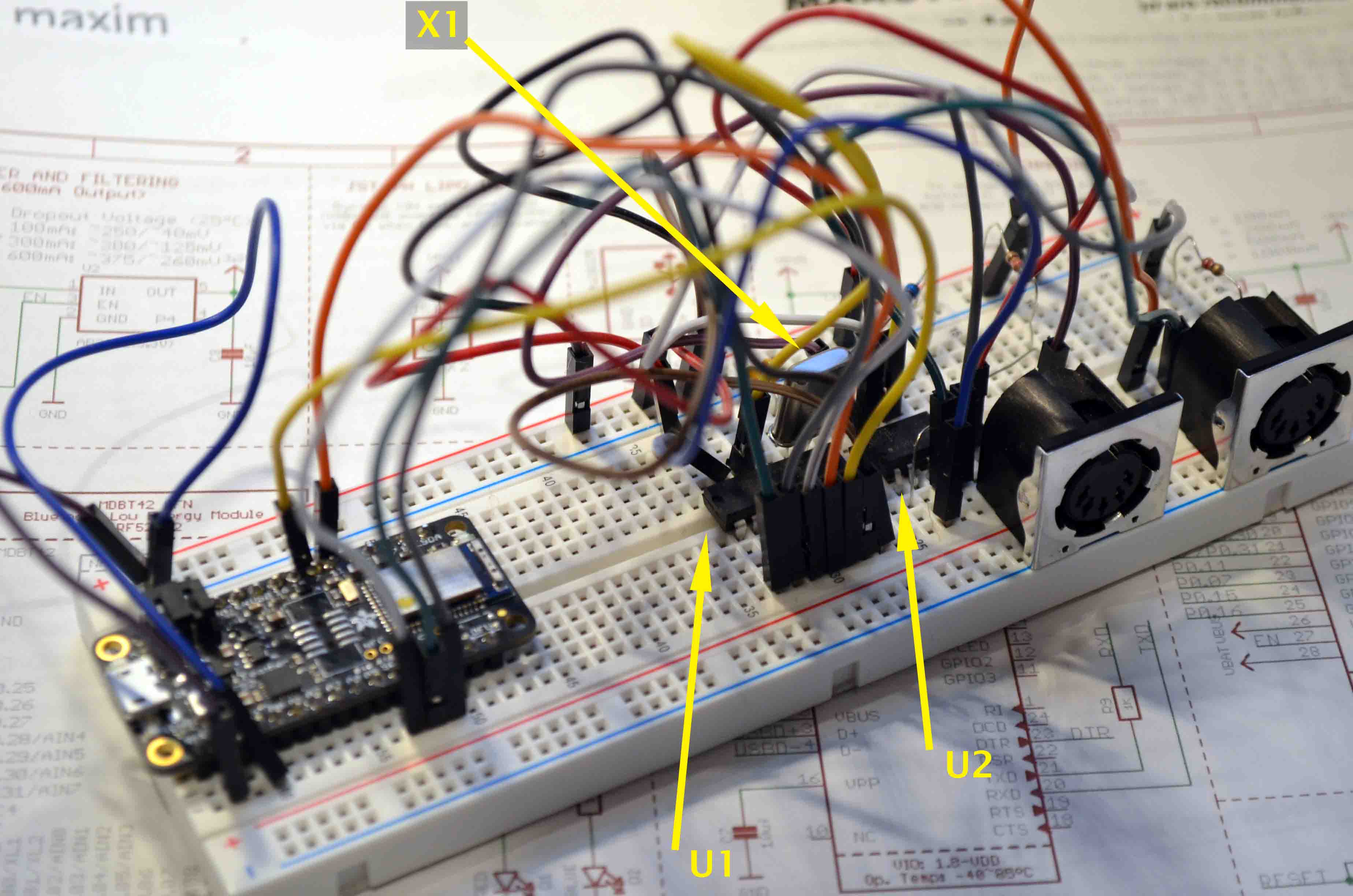
I used the Adafruit nRF52832 development board (which they call a “feather”), for no real reason other than availability. Because I was completely new to microcontroller development, the fact that Adafruit has decent tutorial documentation for their products was important. It has Bluetooth Low Energy (BTLE) capability that I thought would be interesting, though I did not use that in this project. At the time of this writing the microcontroller board is still sold but probably obsoleted by an equivalent product based on the later nRF52840.
The Adafruit board is supported by the Arduino IDE infrastructure, which I leveraged in order to bootstrap the development process. However, one of the first things I did was to strip away the Arduino layer: while this common abstraction is helpful in getting things up and running, it obscures the reality of what is actually going on underneath.
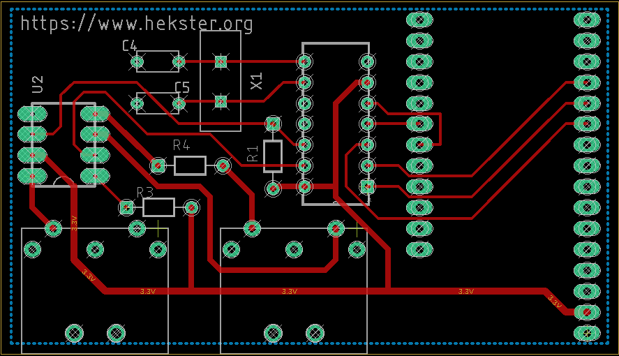
Since I would be prototyping on a breadboard anyway, and since I have zero experience using surface-mount devices (SMD) I took the constraint of selecting only through-hole devices. While this does limit selection, there are fortunately still many such devices available.
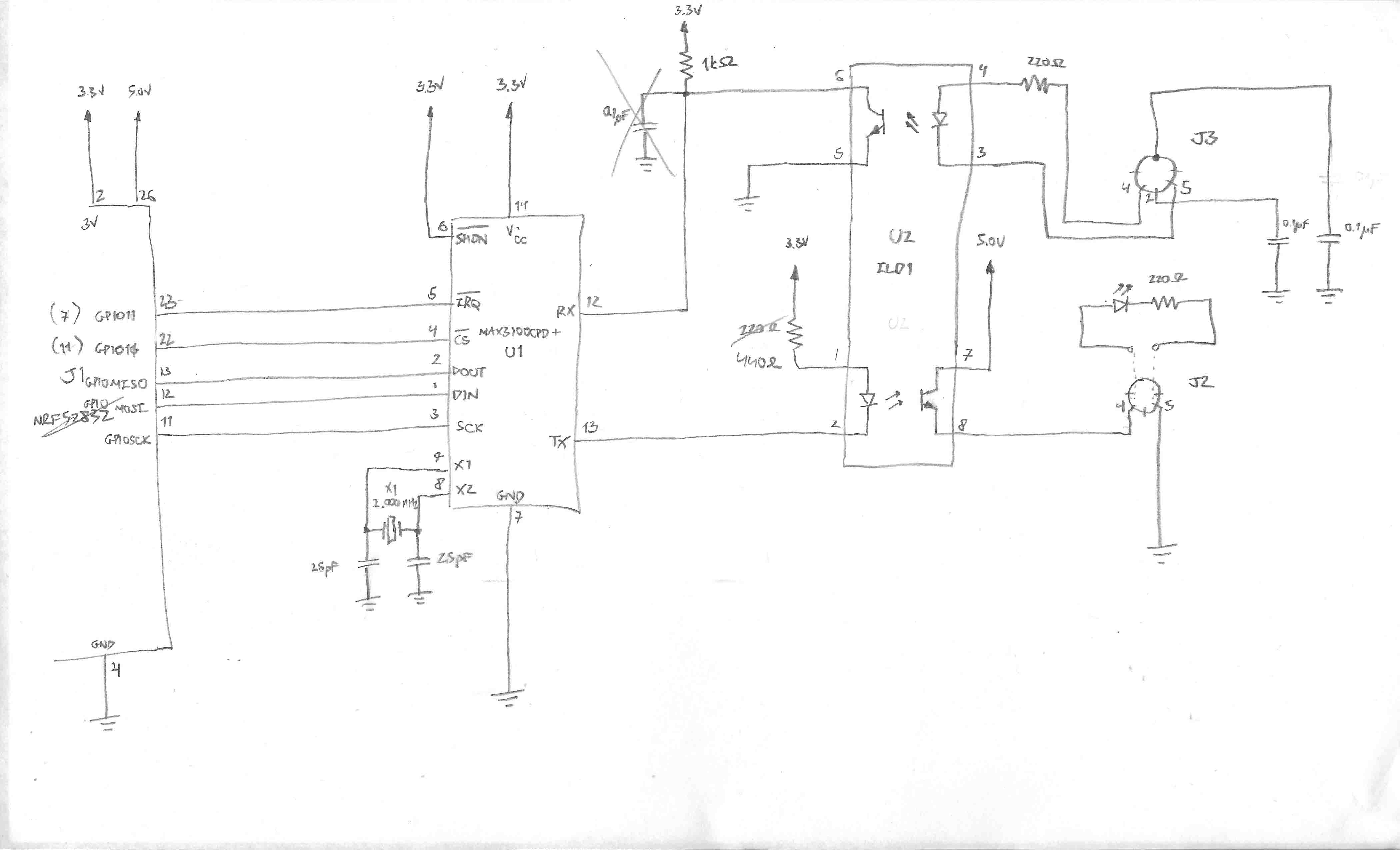
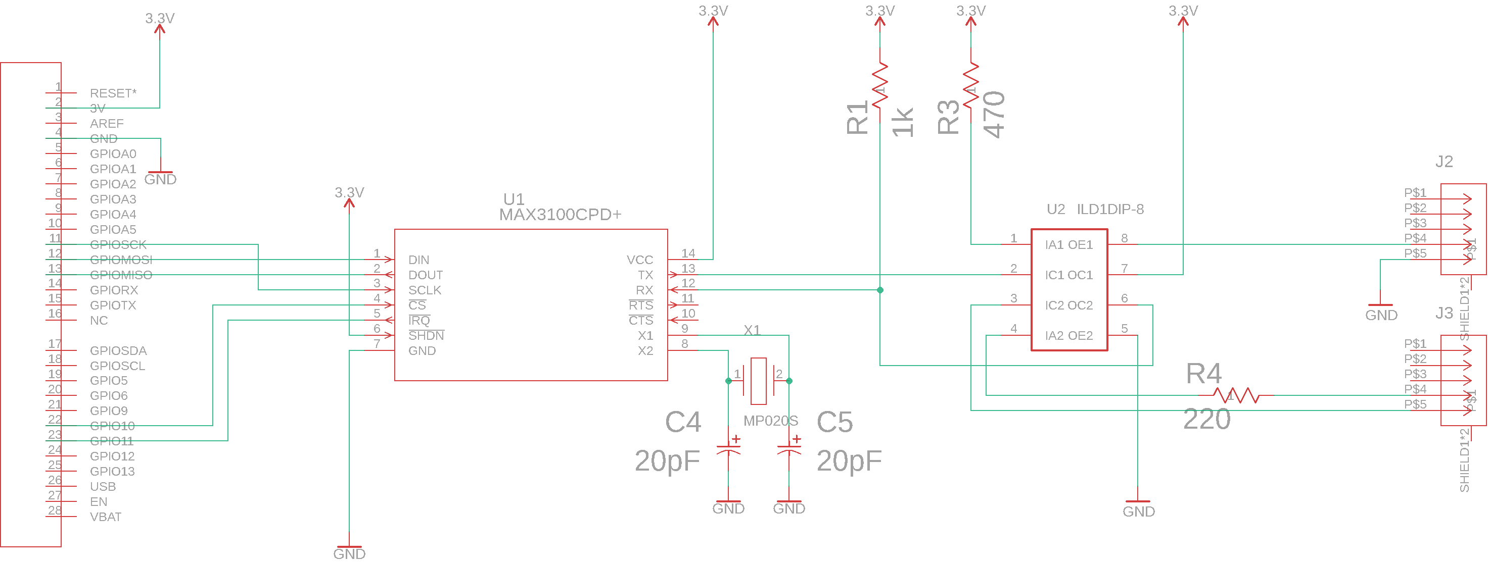
The MIDI electrical interface is nominally a 5mA current loop. However, the official reference design implies the assumption that the receiving end constitutes an optocoupler with a series 220Ω resistor, so in practice a voltage source is always used. For the optocoupler I chose the Vishay ILD1, which is available in a DIP package. Since this package incorporates two optocoupler devices, I took the unusual approach of using one on the transmitter loop as well; I felt that the added electrical isolation was an advantage.
While the microcontroller has a UART, it is used by the Adafruit board to support the USB interface. I expect that we could programatically disconnect the UART module from the GPIO pins used by the Adafruit board and use them to drive the MIDI interface instead, but this would prevent us being able to use USB interface to send diagnostics for debugging. Given that I was specifically building the device in part to analyze the reason for the MIDI incompatibility I needed USB and MIDI to be connected simultaneously. Therefore I decided anyway to add a Maxim Integrated MAX3100 UART dedicated to the MIDI interface that can be driven through the microcontroller's Serial Peripheral Interface (SPI).
All this results in the initial schematic:
Note that while I had originally intended to source the +5V supply to power MIDI output (the idea being to reduce load on the +3.3V supply), I ended up not doing so, for reasons I don't recall. Also I had some bizarre reason for putting a capacitor on the MIDI input optocoupler collector; again, I don't recall why I thought that would be a good idea, since it essentially filters out high frequency signal— which is the opposite of what is needed. I verified that the circuit does not work when it's present, and removed it from the final design. Similarly I had some notion of adding capacitors for ground noise filtering on the ground pin and shield of the MIDI IN connector, but decided to remove them since I'm not relying on a ground voltage and I couldn't really justify what purpose they would serve.
For example, to start playing/recording MMC sends
F0 7F 7F 06 02 F7while the corresponding System Real-Time message is simply
FA
Both of these are specifically documented in the original MIDI Specification Document version 1.0 from 1996. It's not clear to me how the two types of messages are supposed to interoperate, or whether they are even supposed to; but my specific problem could now be solved simply by translating from one to the other type.
Things to note:
All pages under this domain © Copyright 1999-2021 by: Ben Hekster