This documents my experiences building a microcontroller-based radio panel for use with the
X-Plane flight simulator.
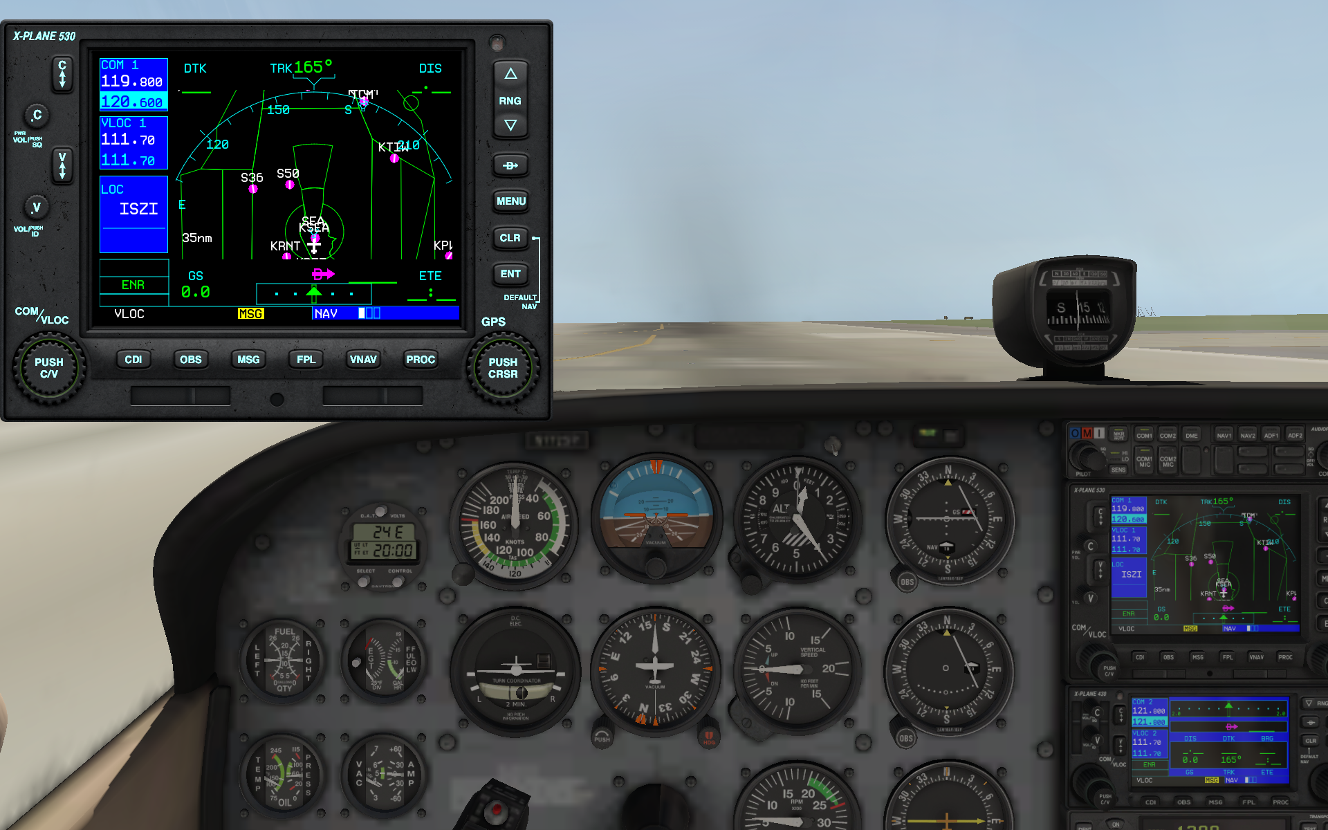
The panel simulates an actual general aviation ‘COM’ radio, such as one you might find in a Cessna 172 Skyhawk:
it displays the ‘main’ frequency the radio is tuned to, and a ‘stand-by’ frequency that can be modified by
‘dialing in’ with a knob.
A switch swaps the dialed-in stand-by frequency with the main tuned frequency.
The idea is that one would use the panel to control the simulated radio instead of using the keyboard/mouse.
This is my second microcontroller project, building on the experience gained in my previous project prototyping a MIDI processor.
Declaration
I have no personal interest in any of the companies or products mentioned here;
I am not and will not be compensated in any way for using any of the products.
My intent is simply to describe my personal learning path through the wide and complex technological field
of embedded systems development, in the hope that it can be of help to somebody.
Objectives
The primary ostensible objective is to design and construct a prototype of a panel as described above.
Secondarily, also:
-
Learn more about embedded systems development; specifically, I want to understand as much as possible about what is going on.
This means I will remove any abstraction layers that I don't find useful.
-
Learn more about the foundational technologies ARM, USB, SPI.
-
Experiment with using C++ for embedded programming and determine its usefulness.
-
Build something that makes X-Plane even more fun to use!
Environment
Nordic Semiconductor
As in my previous project, I did decide to go with a Nordic Semiconductor
development board from Adafruit again.
I would not use Adafruit again.
Their nRF52832 board seems to be obsolete in favor of a newer one based on the nRF52840.
I have really come to appreciate the Nordic devices and the developer documentation, which is rather good.
However, the decision to use this microcontroller for this project makes no sense and is a cop-out:
it is overpowered and has way more functionality than what is needed.
However, I felt I was facing enough challenges and making enough changes that I didn't want to introduce another variable.
Visual Studio
For my development environment, I continued to use Microsoft Visual Studio (the free Community Edition) on a PC,
as I did in my previous project.
While I'm comfortable using XCode on the Mac or on Linux, this is what I use for day-to-day work and I saw no reason not to use it again for this project.
Also:
Visual GDB
In my previous project I used Visual Studio essentially as a text editor; the builds themselves were just DOS command scripts that
invoked the toolchain directly.
For this project I purchased Sysprogs Visual GDB which is a Visual Studio extension.
I'm very happy with this product: it does a good job integrating with Visual Studio and its project structure.
The integration isn't perfect in the sense that it tends to have its own 'private' setting windows that feel 'outside' of Visual Studio.
I think this is a consequence of the fact that it's using the GDB rather than the MSVC toolchain.
The debugger integration is nearly seamless.
While it certainly is possible to work without an IDE-based debugger (using tricks like LED signalling), in terms of productivity there is simply no comparison.
I wouldn't approach any embedded project that is anything more than trivial without a debugger.
But perhaps best of all is how well it has integrated with the myriad of first- and third-party vendors' technologies:
when setting up a new project for a specific device it will offer to download whatever dependencies are needed.
This is an amazing benefit when getting acquainted with first setting up
J-Link Segger
Also, I purchased the J-Link Segger EDU Mini for programming and debugging.
This means that I'm no longer dependent on mysterious bootloaders pre-programmed on my microcontroller and what I consider to be USB mass storage simulation
'hacks' perpetrated by the likes of UF2;
I just flash exactly what I want onto the device, and nothing more.
This also means that the USB interface of the development board is now usable by my application since it isn't hijacked to do programming anymore.
I don't like mystery software that gets between me and the hardware; or being dependent on vendors preprogramming their bootloaders.
It integrates perfectly with Visual GDB for both programming and debugging.
Picoscope
Finally, I purchased a Picotech Picoscope PC-based oscilloscope for circuit debugging.
It is nearly impossible to diagnose hardware problems without one.
In this case, I was at one point running into serious problems communicating with the display driver;
the scope helped me see that this was due to a supply voltage problem because of a badly placed jumper wire.
In my previous project I was able to use the microcontroller's own DAC as a poor man's oscilloscope,
but for anything even slightly above trivial this is impossible.
I considered an actual desk oscilloscope but the cost of those was prohibitive.
In the end I am very happy with the Picoscope, and it is probably easier to use than a desk scope.
Tortoise SVN
My source control is a local Subversion server hosted on my NAS device.
I use TortoiseSVN Windows 'shell' integration in my desktop environment.
I did briefly use the VisualSVN integration in Visual Studio, but my PC is frankly not powerful enough to deal with all the extensions as it is
and since it didn't seem to offer much more, I removed it and just used Tortoise directly.
Architecture
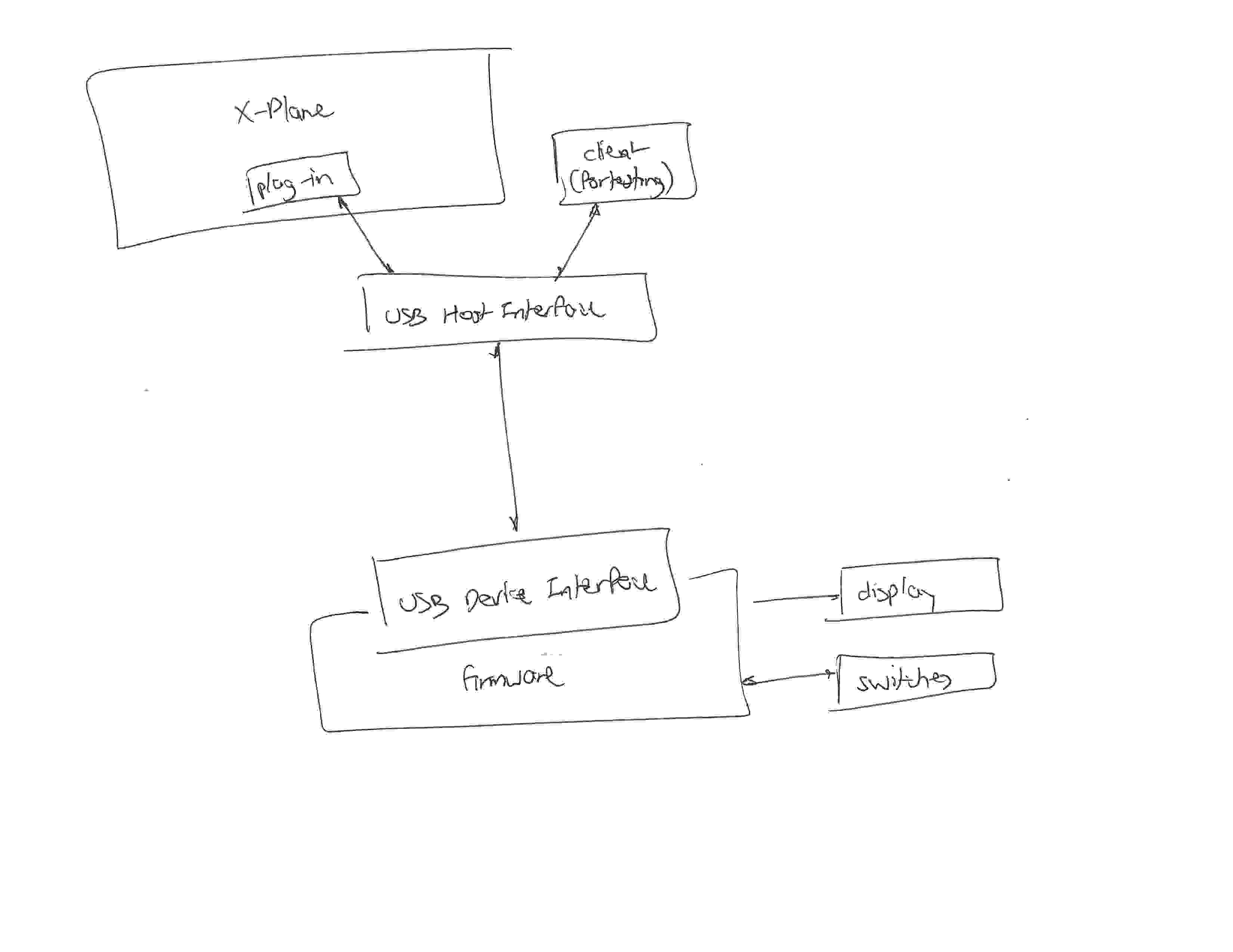
The panel presents itself as a USB device; this seems a blatantly obvious choice and allows us to leverage the existing hardware and software infrastructure.
USB interrupt.
This requires supporting firmware on the panel.
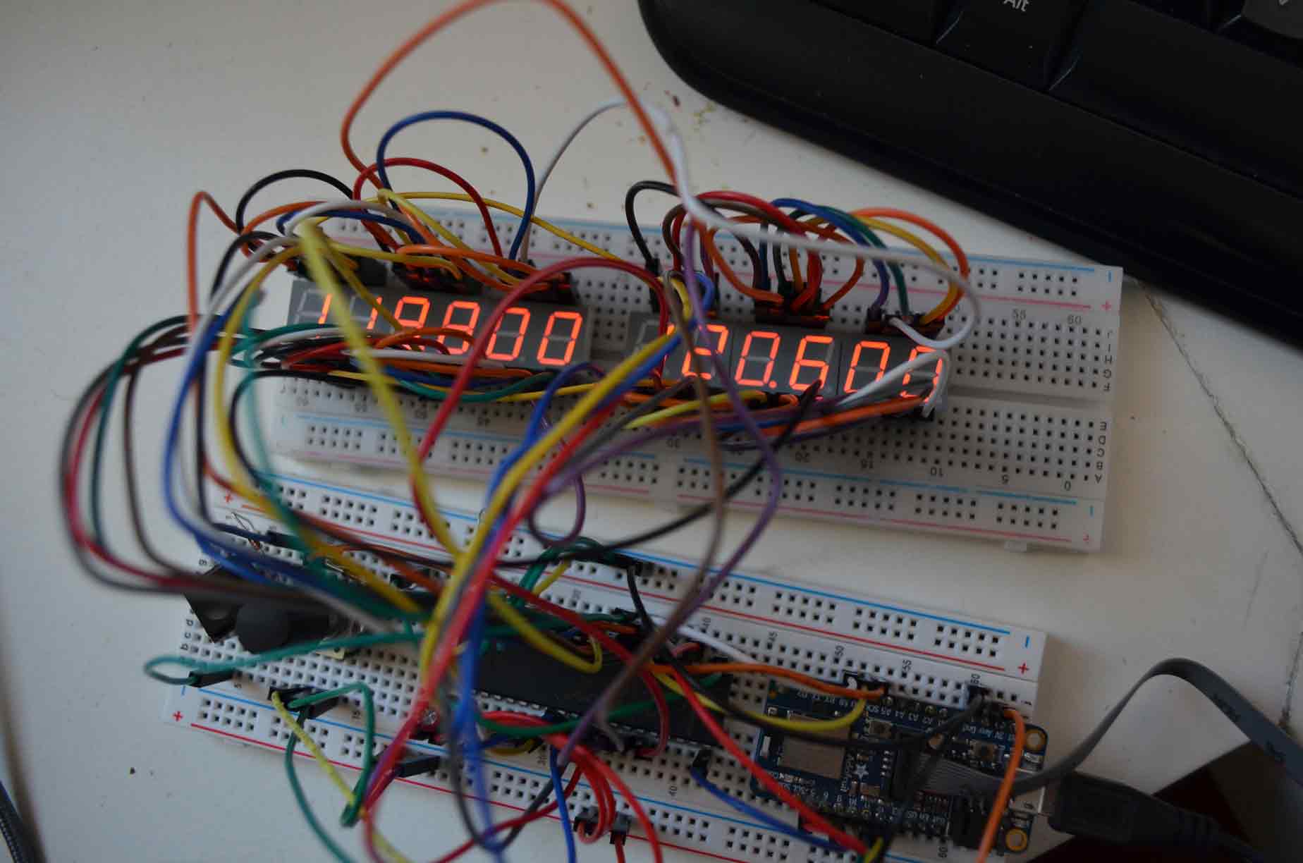
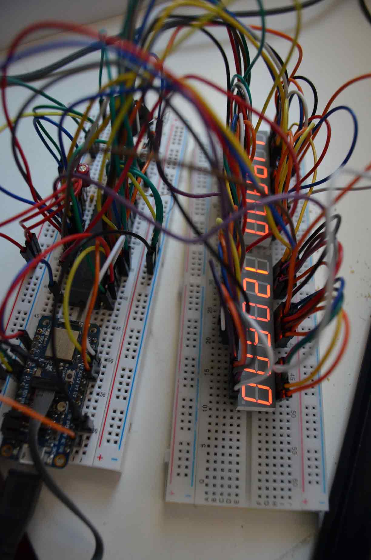
The panel also contains the display; I wanted amber-colored seven-segment LEDs for realism.
Circuit Design
All the electronics had to be through-the-hole and DIP:
I wasn't willing to embrace the additional challenges of conquering LQFP soldering at this time.
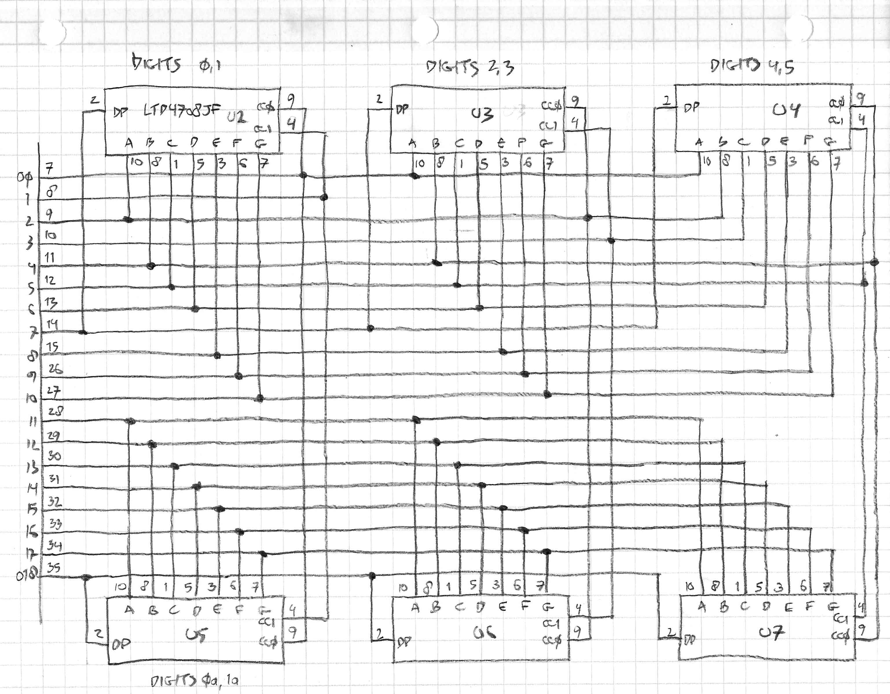
Display
We need two 6-digit displays with support for a decimal point.
There's no shortage of them; I selected the LTD-4708JF 10mm yellow/orange duplex 7-segment from Lite-On.
Initially I used four triple-digit components until I ran into trouble when I realized that the 6954 can only drive
dual shared-anode displays. I hacked around it for a while until I replaced them with six 2-digit display components.
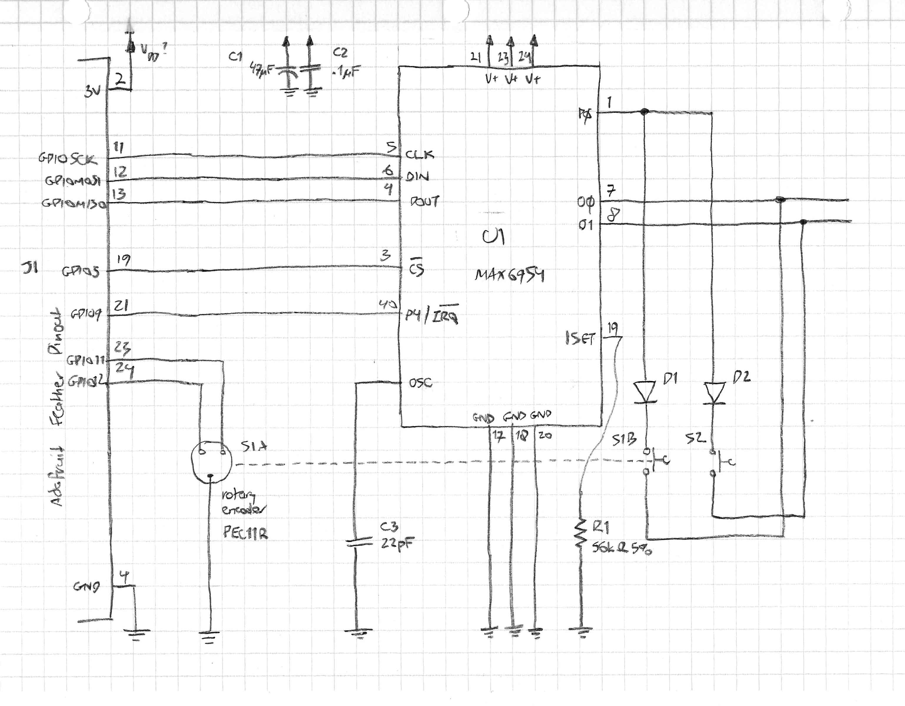
Display Driver
The immediate question that arises is how to drive the LEDs.
I think with a different choice of microcontroller it might be possible to drive this with GPIOs; but I liked having a custom display driver.
I found the MAX6954 from Maxim Integrated perfectly served the purpose.
It interfaces with the microcontroller over SPI.
In addition to driving all twelve 7-segment digits, it also supports interfacing with and debouncing switches with processor interrupt capability.
The massive simplification of driving the displays and switches increases component count and cost and with the 40-pin DIP package, ultimately, PCB surface.
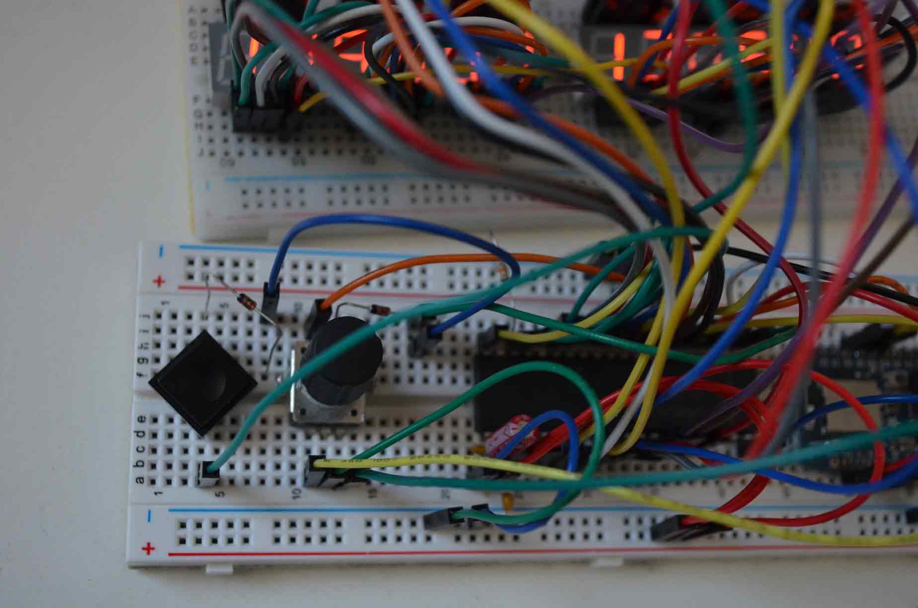
Switches
Rotary encoder needed for frequency selection.
A real avionics radio panel selects the unit MHz frequency with one ring (typically, the outer) of a knob
and the decimal portion (in 1/40 or 1/120 MHz steps) with another (inner) ring. I wasn't able to readily locate such
a switch; so instead I selected the PEC11R encoder from Bourns which has a push switch built in to the knob. Unit MHz
are selected by default, fractional MHz are selected when rotating the encoder while pressing it. It's not ideal
but good enough.
The rotary encoder is connected directly to the microcontroller GPIO;
fortunately the Nordic has the necessary 'quadrature decoder' support built into hardware, again greatly simplifying dealing with this component.
The push-button portion of the switch and its debouncing is handled by the Maxim display driver.
A simple push-button switch is used for swapping active and stand-by frequencies.
This again is handled by the display driver.
Schematic
Firmware Design
The Nordic SDK has a layered organization; I avoided all the 'driver' layers (other than using them as code examples)
and went straight to the hardware abstraction layer (HAL).
I don't quite see the point of doing run-time error checking.
A more elaborate project probably deserves some kind of RTOS; I don't think this project rises to that level yet.
The firmware is essentially an event loop, driven by ARM Cortex events.
The peripherals of the Nordic microcontroller (and I'm guessing every other ARM-based microcontroller) are closely
integrated with the ARM Cortex interrupt and event system.
This design allows the device to sleep until an event occurs.
The USB descriptor data structures are very elaborate.
I found that C++ allowed me to explicitly express the structures with no overhead.
Implementation
I like Subversion and feel that Git doesn't really improve on it; certainly not in a single-user environment.
However, in the context of open-source development Github seems to have taken over;
so I have created a repository there
and will try manually synchronizing between the two.
Demonstration
Observations
X-Plane appears to have multiple overlapping and redundant 'data references' for the radio;
unfortunately the ones that I found to work have 10 Hz resolution so don't give me control
over the last decimal.
C++
I am now completely convinced that C++ is an excellent (perhaps the best) choice for firmware coding.
Using C++ for its abstractive and reuse capabilities is a success.
I was able to use the Curiously Recurring Template Pattern
(CRTP) as a compile-time inheritance mechanism.
USB
USB is a vast and complex set of protocols; the USB 3 extensions seem to have turned it into a mess.
Next Steps
Using an evaluation board obviously makes no sense in a finished product;
but confronting this may require me to develop some phenomenal soldering skills.
Also, the Nordic processor with its radio and Bluetooth support is not the right choice for this particular application;
though I am looking forward through to trying out these features in another project.
At some point it would also be nice to see this work on the Mac version of X-Plane.
The radio panel is just one example; you could imagine building the rest of the cockpit avionics as well: switches, attitude indicator, etc.
I might consider using a proprietary (non-ARM architecture); there are no DIP ARM chips anymore.
Enclosure; requires mechanical engineering.
References
- nRF52840 Product Specification v1.2; Nordic Semiconductor
- USB Complete, 4th ed.; Jan Axelson; Lakeview Research LLC
- The Definitive Guide to ARM Cortex-M3 and Cortex-M4 Processors; Joseph Yiu; Newnes
- X-Plane SDK
All pages under this domain © Copyright 1999-2022 by:
Ben Hekster