⚠ The information on this Web site is intended as a study guide, and clearly not as a substitute for official sources.
Background
I'm experimenting with developing a consistent diagram style for modeling complex systems;
I've been using such diagrams naturally as part of my job in software engineering, but have found
them to be useful in other settings as well (such as electronic music equipment).
In this case, I found the KAP 140 autopilot found in my 172S trainer non-intuitive, and
a cursory reading of the Supplement wasn't enough; so I decided to dig in and extract the essence
into a more easily-understood diagram.
It's important to realize that there are (to my knowledge) three different hardware variations of the KAP 140:
- single-axis (roll); described in my POH in Supplement 7 of Section 9
- two-axis (roll and pitch); described in Supplement 15
- two-axis with altitude preselect; described in Supplement 15 from page 12 onwards
In addition, the two-axis variant (with or without altitude preselect) has a software modification
as per a required Service Bulletin (Honeywell KC 140-M1) that affects the user interface.
The diagram here refers to the last of the three hardware variants with the service bulletin applied.
Also, I've only incorporated modes relevant to VFR (so the APR and REV lateral modes
are not shown).
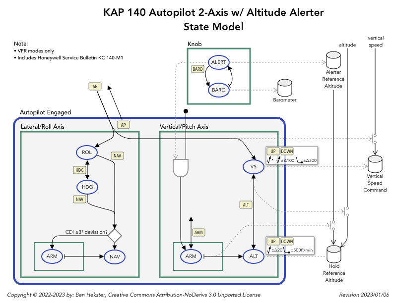
Explanation
The blue rounded objects are meant to indicate ‘states’ that the autopilot can be in;
i.e. ROL and HDG states of the lateral mode, or even the large blue ‘Autopilot Engaged’ state:
what wasn't originally clear to me is that the KAP 140 has a function (the ‘altitude alerter’)
that operates continually, independently of whether the ‘autopilot’ function proper is engaged.
This is what I've attempted to clarify with the explicit 'Autopilot Engaged' state in the diagram.
The green rectangles indicate independent ‘state machines’. Specifically here, when the autopilot is engaged the
lateral and vertical states are both active and operate independently of one another; so laterally you might be
in ROL mode and vertically in the ALT mode. This also hopefully clarifies another point of confusion
that I had, which is that it isn't possble for only (say) the lateral mode to be active and not the vertical mode.
The solid line arrows represent state transitions: usually these are triggered by button pushes,
indicated either by the tail end of the line being connected to the source state, or it floating within
the enclosing state machine in the case that the transition can be triggered by any state in that machine.
The lines with a ‘flat’ tail that is disconnected from the source state indicates transitions
that happen for reasons other than an explicit user action (button push); for example, the ARM
states are exited automatically by the system when given external conditions are met.
The dotted lines are intended to show triggers that are not state transitions, although I agree that
this concept isn't yet clearly developed. For example, when the Vertical Mode ARM state is exited,
there is a dotted line that attempts to suggest that the Alerter Reference Altitude is copied to the
Hold Reference Altitude.
All pages under this domain © Copyright 1999-2023 by:
Ben Hekster